| I. | Introduction |
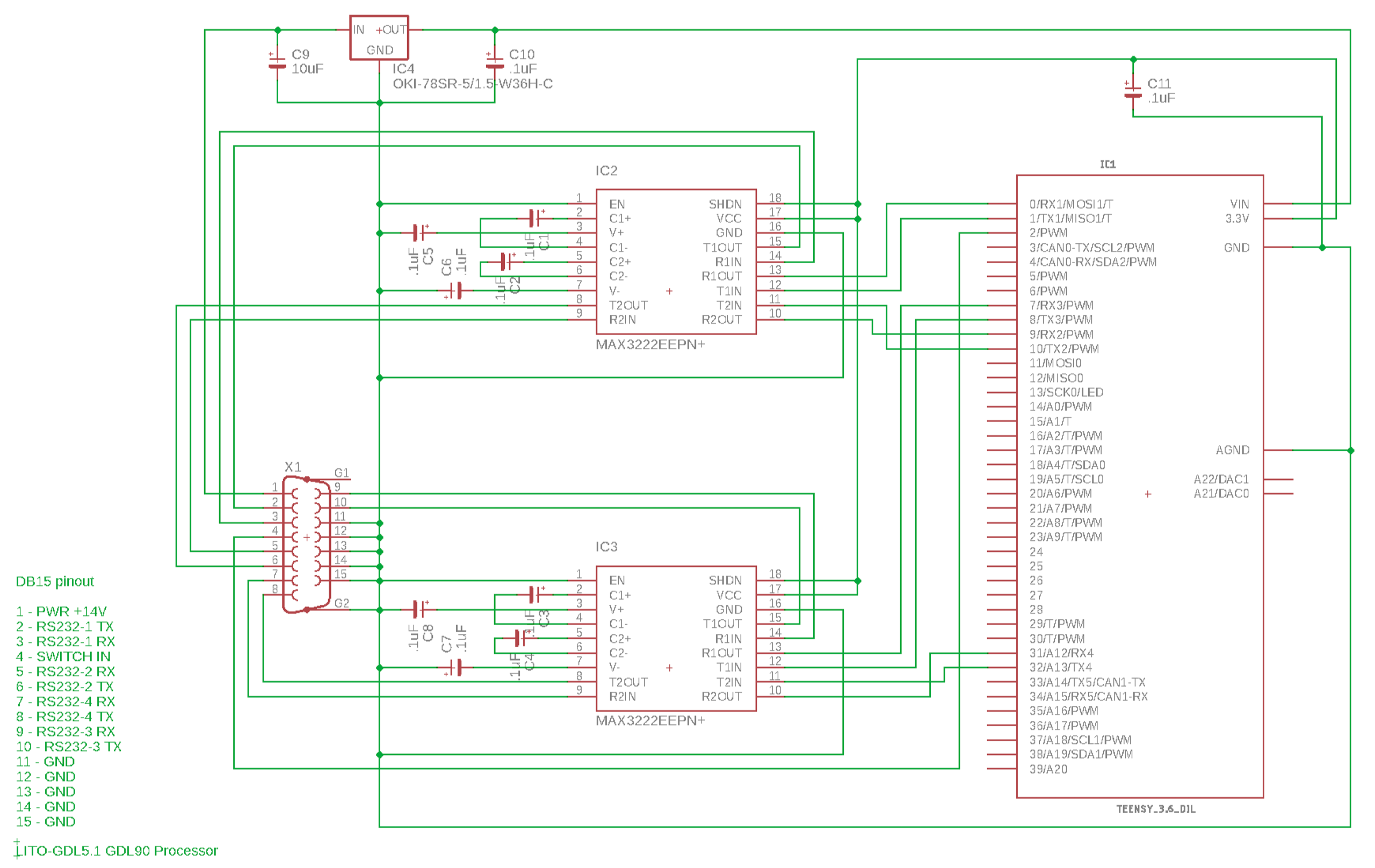
| II. | The Hardware |
| III. | The Shopping List |
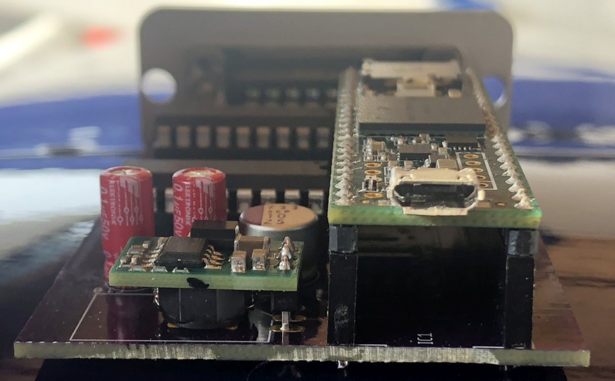
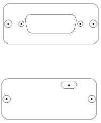
| IV. | Assembly |
| V. | Programming |
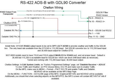
| VI. | Wiring Connections |
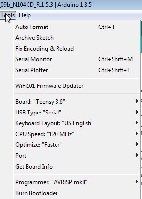
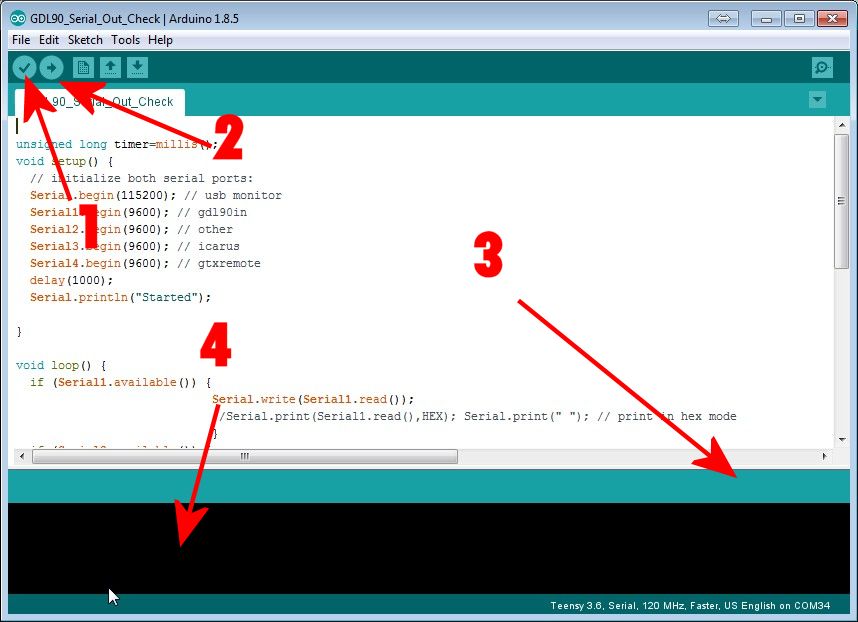
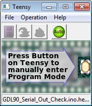
| VII. | Uploading Code |
| VIII. | THE Code |
| IX. |
Traffic Alerting Algorithm |
| X. | Required Setup |
| XI. |
Integrating "The Box" into your
Airplane |
| XII. |
A word about the project |

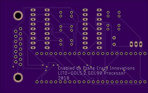 Board Bottom |
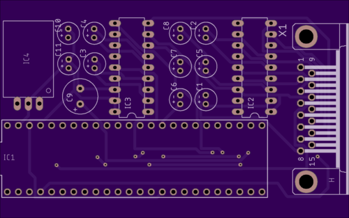 Board Top |
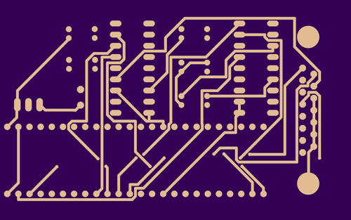 Board Bottom Layer |
 Board Top Layer |
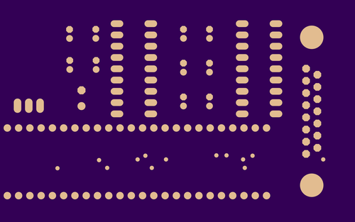 Board Bottom Soldermask |
 Board Top Soldermask |
 Board Bottom Silkscreen |
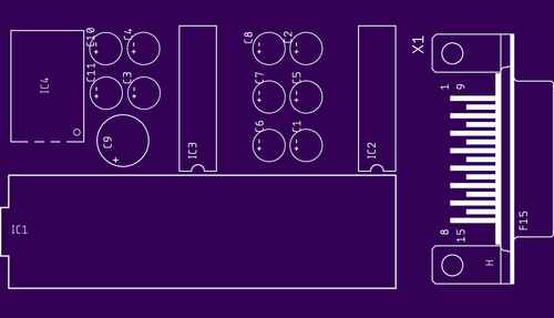 Board Top Silkscreen |
 Drills |
Quantity |
Approx Price |
Description |
Digi-Key p/n |
Mouser p/n |
| 1 |
$31 for 3 |
Oshpark Circuit Board |
||
| 1 |
$8 |
2.54mm Header Pins 40-pin Female | Amazon
Link |
|
| 1 |
$5 |
Murata OKI-78SR-5/1.5-W36H-C 5V DC/DC Converter | 811-2692-ND |
580-OKI78SR51.5W36HC |
| 1 |
$2 |
Panasonic 25SEP10M Capacitor
(Used for C9) |
P16317-ND |
667-25SEP10M |
| 2 or 10 |
$.12 |
Wurth WCAP-ATG5 50V .10uF capactitors
860020672001 (Note: You can use these *or* non-polarized Ceramic on the RS232 ICs; use these on the input power filter C10 and C11) |
732-8847-1-ND |
710-860020672001 |
| 0 or 8 |
$.40 |
Murata RCER71H104K0DBH03A 0.1uF
+/-10% 50V Ceramic Capacitors X7R (Automotive Grade) (These are good to use on the 8 spots required by the MAX3222 IC: C1 thru C8) |
490-7514-1-ND |
81-RCER71H104K0DBH3A |
| 2 |
$6.50 |
MAX32222EEPN+ RS-232 3-5.5V 250kbps transceiver | MAX3222EEPN+-ND |
700-MAX3222EEPN |
| 1 |
$3.60 |
Harting D-Sub board mount Female 15-pin connector 09682537612 | 1195-5133-ND |
617-09682537612 |
| 2 |
$2.00 |
Mill-Max 18-pin gold plated IC Socket 110-43-318-41-001000 | ED90035-ND |
575-11043318 |
| 1 |
$2.00 |
15-pin D-Sub Backshell 86303638BLF | 609-1425-ND |
649-86303638BLF |
| 1 |
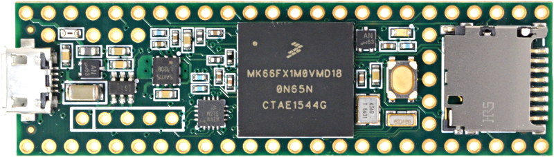
$37.00 |
SparkFun Teensy 3.6 WITH Header Pin Board | 1568-1465-ND |
474-DEV-14058 |
| 1 |
$13.00 |
Hammond 3.2x2.2x.91" Extruded Aluminum Enclosure 1455C801 | HM969-ND |
546-1455C801 |
| 1 |
$.80 |
Cinch D-Sub Connector 15-pin Male 40-9815M
(To mate to "the box") |
367-1190-ND |
601-40-9815M |
| 2 |
$.30 |
4-40 thread Female Screwlocks 5207953-3
or 5748558-3 or similar (Or pull them off a junk
PC for free) |
5207953-3-ND |
571-5207953-3 |
| 1 |
$.50 |
Schottky Diode 20V 3A DO201AD 1N5820/E3/54
(To put inline with power wire) |
1N5820-E3/54GICT-ND |
625-1N5820-E3/73 |
| Additional Optional Parts You May Want |
||||
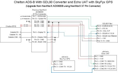
| Optional Parts you may want or
need: If you're converting an old NavWorX ADS600B, you
may want to buy a 37-pin connector and backshell similar to
(3-199-1253-7) to use to connect to all of the Echo UAT
components and "the box". Also, Kapton tape for
protecting the pins from the enclosure. (or use packaging
tape) D-Sub machined pins for the box connector (Pins
such as 204370-8 or MilSpec M39029/64-369 are not
included in the above). (Alternate Pin source:
SteinAir SA-1018) Echo Molex connectors 0436450600
and Pins 0462350001 for adding wires to the Echo
Harness. (Mouser and Digi-Key Sell the molex
parts) If you want to join the 37-pin connector shell
to another mating connector, you may want these hex nuts
Conec 160X10379X or Digi-Key 626-2113-ND. |
||||
 |
 |
 |
 |
 |
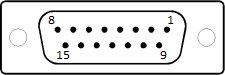
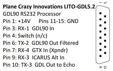
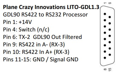
| Pin |
Function |
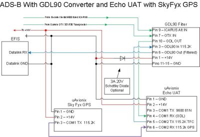
| 1 |
+14V Power |
| 2 |
Transmit 1
- Unused |
| 3 |
Receive 1
- GDL90 Traffic/Weather In from Echo |
| 4 |
n/c |
| 5 |
Receive 2
- Unused |
| 6 |
Transmit 2
- GDL90 Out - Filtered - To Display/EFIS |
| 7 |
Receive 4
- GTX In from Garmin 327/330 Xponder |
| 8 |
Transmit 4
- Unused |
| 9 |
Receive 3
- ICARUS Baro Alt In from Encoder |
| 10 |
Transmit 3
- GDL (SL-70) Baro+Squawk to Echo |
| 11 |
GND |
| 12 |
GND |
| 13 |
GND |
| 14 |
GND |
| 15 |
GND |
| SETTING |
Description |
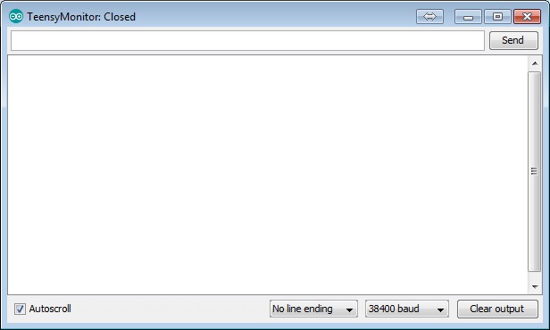
| #define DEBUG |
This is commented out by default but if un-commented it will allow you to monitor the micro-usb in-flight and see what's happening on the serial monitor |
| #define GDLCONTROL |
This is active by default and enables the
processing of the Altitude Encoder and Transponder
communications inputs and outputs. Note that this ONLY
uses ICARUS altitude format, and GTX transponder control
format, and ONLY outputs SL70 (GDL) format. |
| #define SHADINZ |
If you are not using ICARUS format, but
getting SHADINZ format such as from a GRT EFIS for your
altitude encoder, you may need to disable ICARUS and use
SHADINZ format in. |
| #define ICARUS |
Uncomment this option if you are using a
standard ICARUS format Altitude Encoder for Baro Alt. |
| #include "Aircraft_Settings.h" |
This is new in version 1.6.0. It allows
you to have a separate file where you keep your tweaked
settings for your aircraft. This way if you want to
change things during testing, you can save various versions
of this file and simply load the one you want. The
filename can be change to whatever you want...suggest using
your N-Number, but make sure to change the "include" line in
the .ino file to match the filename. |
| #define FRIENDS |
This is active by default and enables you to
have "Friendly" targets (Other airplanes) that will NEVER
give you traffic alerts. If you fly formation, it is
handy to not constantly have traffic alerts while you fly
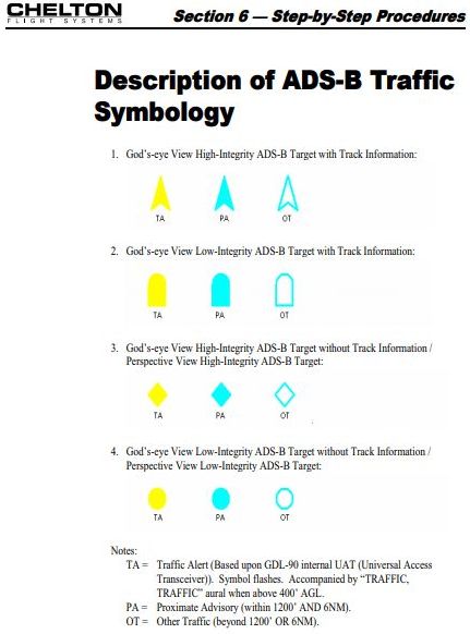
with them. Additionally it will, on the Chelton EFIS
at least, display the friendly targets as a different symbol
type, whenever they are over a mile away from you.
This makes it easier to find your friends and join up with
them. |
| int32_t ownModeSCode= |
Example: int32_t ownModeSCode=0xABC123 This is where you enter your own airplanes ICAO Code. You prefix it with "0x" The ICAO Code needs to be the HEX version, NOT the Octal version, from the FAA site. Whatever ICAO code is listed in this setting will never be displayed as traffic on the output data stream. |
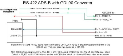
| int gdl90_outbaud=38400; |
This is the baud rate used for the output
GDL90 Data Stream to your EFIS |
| int gdl90_inbaud=115200; |
This is the input baud rate from COM2 of the
Echo UAT or other system into "The Box" |
| int icarus_inbaud=9600; |
This is the baud rate of your Altitude
Encoder's ICARUS Altitude |
| int gtxremote_inbaud=9600; |
This is the baud rate of your GTX327/330
Squawk Signal |
| const int outputBufferSize=3456; |
This sets some internal buffers for the
processing: gdl90_outbaud* 0.9; 10368 for 115200bps;
3456 for 38400bps |
| bool maintenanceOverride=true; |
This will override the ADSB Maintenance flag
if there is a problem with the system. It should be
"false" by default but if you aren't using GTX and Altitude
Encoder inputs, it may need to be "true" to prevent spurious
alerts due to the poor function of transponder monitor on
the Echo. |
| Ghost Filter
Settings |
|
| float ghost_dist_diff=0.25; |
This is the distance in miles that shadow
targets (Ghosts) will be filtered out. Shadows caused
by being primary targets to radar have a different ICAO code
format, a "Track File ID" instead of an ICAO number.
We will not display airplanes that could be your own
airplane, in a close proximity to you, if they are a
trackfile ID. |
| float ghost_alt_diff=200; |
This is the difference in altitude that the
track file ID shadow target will be filtered out, relative
to your altitude. |
| float ghost_track_diff=45; |
This is the track difference from your own
track that helps identify a shadow target. If they are
on approximately the same track, it is probably you, and
should be filtered. Reduce this track angle to make it
more sensitive and not filter shadows as easily. |
| Traffic
Alert Settings |
|
| int32_t alert_alt_diff=400; |
This is the altitude difference maximum that
a nearby target must be, for it to cause a traffic
alert. Straight and level traffic that is more than
this value above or below your altitude will not
alert. To alert on airplanes more easily, expand this
value. |
| int32_t alert_fuzzy_alt_diff=950; |
This is the altitude difference maximum that
a target will be, to cause an alert, if either it, or you
are climbing or descending. It us used in the
projected altitude functions to estimate if you will be
coming together with the other aircraft and be close in
altitude if you continue your trajectory. If you want
to have more alerting if you will be close in altitude when
you meet another plane, expand this number. If the
number is too large, you will have many alerts whenever
someone is climbing or descending to your general projected
position, even if they level off at a cruising altitude far
above or below you. That is why 950' was chosen as a
default. |
| int32_t alert_seconds_before=40; |
This is the amount of time that will trigger
an alert when you are closing in on another airplane.
i.e. in 40 seconds or less, you will close in and come
together or have a near miss with the other aircraft.
This is done by time calculation so you will get 40 seconds
warning whether it's coming up fast behind you, or coming
head on in front of you, as it calculates actual "Time to
close" on the intruder. Expand this to get more
warning, but be aware that at 150kts you are traveling
nearly 3 miles in 60 seconds, so a 40 second gives you more
than 4 miles of warning in a head on situation with a
similar speed aircraft. |
| int32_t alert_vector_length=40; |
To explain this, imagine a vector projected
out in front of your airplane, like a very long pitot tube
on your nose. This vector is 40 seconds long, and thus
is longer the faster you go. There are algorithms that
will use this vector ahead to monitor for traffic that will
be crossing paths anywhere along your 40 second vector with
their 40 second vector, like 2 Star Wars warriors with light
sabers. :) Should these light sabers touch, you
will get an alert. Make the vector longer and you will
have a greater look-ahead to traffic that may cross your
path. Make it too long and you will receive many
alerts. Make it too short and you won't get many at
all. |
| float alert_dist_diff=0.5; |
This is the distance in miles that we have a
backup alert for alerting on close proximity that may be
traveling nearly parallel. If the track vectors will
not be crossing, even nearly head-on traffic may not alerts,
and this backup alert will still give you minimal warning
whenever someone is coming near to you. |
| float
positive_closure_distance=1.0; |
This is the distance in miles that will be
alerted as long as a target has a positive closing rate on
your airplane. It is used in conjunction with
positive_closure_max_time for this alert. |
| int32_t
positive_closure_max_time=180; |
This is the time in seconds that a
positive_closure_distance target must be under, before it
will alert. In the default of 180 seconds, a plane
must be coming at you where you will come together in less
than 3 minutes if it is within a mile of your
position. If you are converging so slowly that it will
take more than 180 seconds, it will not alert until it
reaches the alert_dist_diff setting above. This way
you can fly near other airplanes on similar tracks but if
you will not meet for more than x seconds, you will not
receive an alert. |
| Traffic
Tracking Settings |
|
| const int maxIntruders=60; |
This is the number of intruder airplanes that
are monitored in a table of targets. Only targets
within filterAltitudeAbove and filterAltitudeBelow altitudes
relative to you, and filterDistance range from you, are
added to the table. This is simply the number of
airplanes tracked in the table. The table always
sorts in order of distance, so you always are calculating on
the nearest 60 targets, but all of the others beyond 60 are
ignored. |
| const int maxIntrudersOut=20; |
This is the maximum number of targets sent
out on the RS232 stream to the EFIS. 38,400 baud can
only handle 32 targets with 4 uplink messages per
second. By limiting the targets to 20, we can send one
additional uplink message per second, and prevent the EFIS
screen from being cluttered by targets. You can adjust
this as high as 32, but reduce maxUplinkMessages to 4 if you
go higher than 24. |
| Traffic
Filtering Settings |
|
| float filterDistance=80; |
This is the distance in miles that traffic
will be limited to. Any traffic further than this will
not be placed into the traffic table or displayed on the
EFIS. |
| int32_t filterAltitudeAbove=5000; |
This is the number of feet above you beyond
which traffic will not be displayed. It eliminates
high-altitude aircraft from being displayed for you.
You may wish to expand this if you frequently fly near
parachuting operations. |
| int32_t
filterAltitudeBelow=10000; |
This is the number of feet below you beyond
which traffic will not be displayed. It eliminates
low-altitude aircraft from being displayed for you.
The default is set higher so that you can see traffic at the
destination airport many miles out as you descend, but it
may be set to a number as low as 5000' if you do not wish to
see such traffic. |
| Coasting
Settings |
|
| uint16_t coastTime=15000; |
Traffic must report its position every 1-2
seconds to be displayed on the EFIS. If a target
doesn't transmit regularly or your antenna doesn't pick it
up regularly, it will disappear. The coasting
algorithm calculates where a target will be based on its
last transmission. coastTime=X is the number of
seconds to project where this target will be, before simply
dropping it. Be aware that if a target does a rapid
turn, climb, or descent, it may not be where it was
projected to be, so coasting is not perfect, but it is
better than not seeing the target on screen at all.
Keep this to 15000 miliseconds or lower (15 seconds) to
ensure the position is fairly accurate. Reduce it to
minimum to do no coasting or minimal coasting, but expect to
see traffic blink on and off at times. |
| Misc |
|
| maxUplinkMessages=5; |
This is the maximum number of uplink messages
to process in a second. 4 is the GDL90 standard
default. |
| int heartbeatInterval=1000; |
This is a heartbeat packet interval between
the box and the EFIS. It sends one every 1000
milliseconds to keep the EFIS happy. |
| Friendly
Settings |
|
| const int totalFriends=8; |
This is the number of friend aircraft in the
array below this setting. You need this number of ICAO
Codes to match the number of them in the array. And
friends airplanes that you do NOT want to get traffic alerts
on, should be put into the array. Be aware that you
will NEVER get collision alerts on them. |
| int32_t
friendArray[totalFriends]={0xABC123,ABD124}; |
This is the array of friends ICAO
codes. They are inserted with comma separation (no
spaces) if you have multiples. In this example, there are 2, and the above totalFriends value should be 2. |
| float FRIEND_dist_start=1; |
This is the distance within where the
friendly targets will display with the standard
symbol. On the Chelton EFIS, standard is an
arrowhead. A friendly on the Chelton is made by
artificially degrading the appearance of the quality of
their signal, which makes them into a rounded nosed type
symbol. If set to 1, within 1 mile the friendly
will have the normal symbol. Set this number low if
you want to see that symbol all the time. Set it far
if you never want to see it. |
| FRIEND_dist_max=80; |
This is the maximum difference that the
friend type symbol will be displayed. Beyond this
distance it would display with the standard arrow symbol. |
| Alert
Setting |
|
| unsigned long alert_hold_time=10; |
This is a hold timer on traffic alerts.
If you receive a traffic alert, but the airplane changes
course and will no longer be a factor, it will stop
alerting. This holds the alert to continue alerting
even if the algorithms no longer detect a collision. A
setting of 10 holds the alert for 10 extra seconds.
This is done to prevent an alert from stopping and starting
a lot if you happen to go in and out of conflicting paths
with another plane. If you are alerting too long, set
it lower. Too short, set it higher. |